

Name:Inverter ST-750W
INVERTER INSTRUCTION
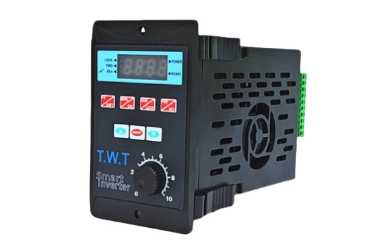
1.1. Display interface description
L1: The red LED flashing button is locked.
L2: Forward indicator light is green (FWD), always on during operation. The LED flashes when forward
rotation is stopped.
L3: Reverse indicator blue (REV), always on during operation. The LED flashes when reverse rotation stops.
L4: POWER indicator, the power indicator is always on.
L5: Rs485 communication instruction.

1.2. Key function explanation
K1 P-K/shift: function parameter display button (P-K/SHIFT). Press the P-K button to query the IPM module
temperature, bus current, bus voltage, motor operating speed, and motor operating frequency. The SHIFT key can
be used for shift selection during setting.
K2 menu/exit: set the enter button (MENUZESC) o MENU button is the function enter button. The ESC key is
the exit key.
K3 save/lock: save/lock button (SAVE/LOCK) SAVE: save, LOCK: lock. Long press to lock or unlock the K2, K3,
K4 keys. After 3 minutes of operation, if there is no operation on the interface, it will automatically lock.
K4 reverse/forward: forward/reverse switching button (FWD/REV).
K5 increment: speed control plus button/data setting plus (t) o
K6 Start/Stop: Start/stop button set confirmation key (RUM/STOP/OK).
K7 Decrease: Speed-Decrease Button/Data Setting Decrease (I)<,
VR panel speed adjustment potentiometer: invalid when setting button speed adjustment and Rs485
communication operation.
2. Function description
2.1. Brief description of the inverter
This inverter is a single-phase 220V voltage input, driving a three-phase motor (be sure to convert the
connection method to a triangular type). Frequency output 1.0-99.0H B In order to increase the output
voltage, this product uses the SVPWM modulation method, the carrier frequency 8.0KHZo is suitable for
motors below 750W, and the maximum output power is 1100W. The inverter can arbitrarily change the V/F
curve by setting the V/F compensation frequency and the voltage ratio at this frequency. By setting the
maximum value of the V/F curve, according to the load, the efficiency of the electrical energy is maximized,
the heat of the motor is reduced, and the service life of the motor and the inverter is extended.
2.2. Internal parameter setting
2.2.1. Operation interface description
The function parameter display content is as follows:
1. Items that can be queried by the K1 key
A. t-xx: displayed as the temperature value of the radiator,
B. Cx-xx: displayed as the current value.
C. xxx.x: Displayed as DC bus voltage value.
D. xxxx: displayed as the motor speed.
E. Fxx.x: Displayed as running frequency value.
2. E-x.x: indicates a fault, refer to the fault code to determine the cause of the fault.
3. The power indicator flashes during the setting interface and startup, indicating that the machine has successfully
communicated with the external Rs485.
4. The button has no operation for 3 minutes, and the power light flashes. At this time, K2, K3, and K4 are locked.
To unlock, press and hold the K3 button for 5 seconds.
5. Running indicator lights FWD, REV, flashing means stop; long light means moving in this mode.
2.2.2. Description of setting interface
When you press the K2 (MENU) button, the digital tube flashes -0.0- through the digital setting
plus or minus button (f) (1), adjust to select the setting Main code to enter, see (Table 1)
During the setting process, you can adjust the code to be set by the digital setting shift key (K1)
and the addition and subtraction buttons (1) (1). After the code is set, press the Enter key (K6) to
enter the item code selection . After the sub-item code is selected, press the K6 key to return to
the Main code interface, the flashing -X.X- is displayed, then select the next Main code, and then
press the K6 key to enter the sub-code selection.
When all the setting options are completed, press the data setting save key K3 to display the
flashing SAVE, then press the data setting save key K3 (SAVE) again to confirm the save, the
interface stops flashing and the data is saved. After starting the inverter, it can run according to
the set data, without power off and then on. When you do not want to save the data, you can
press the menu setting exit key K2 (MENU/ESC) to exit without affecting the previously set
parameters, or after no key operation for 20S, it will automatically return to the running
interface.
No. | CODE | Content | Sub-item code |
Default value |
1 | -0.1- | Set startup time | Setting range: 1-15 (time range: 5S-0.1S) | 7 |
2 | -0.2- | Set stop time | Setting range :1-15(time range:5S-0.1S) | 7 |
3 | -0.3- | Minimum frequency compensation | Setting range :5-15 | 8 |
4 | -0.4- | Set max of compensation frequency | Setting range :5.0-30.0HZ | 20 |
5 | -0.5- | Set the maximum compensation frequency and voltage ratio | Setting range :25-85 | 55 |
6 | -0.6- | Maximum frequency limit Voltage ratio | Setting range :80-128 | 128 |
7 | -0.7- | Rs485 baud rate | 0:48(4800) 2:192(19200) 1:96(9600) 3:384(38400) | 96 |
8 | -0.8- | Rs485 format, ASCII | 1: 8N1 3: 8E1 2:8N2 4:801 | 8N1 |
9 | -0.9- | Aircraft number | 1-255 | 1 |
10 |
-1.0- |
Working frequency source | 0: Panel keyboard control |
1 |
1: Panel potentiometer control | ||||
2: External analog signal input (output voltage is 0-5V) or external potentiometer | ||||
3 : RS485(RS485) | ||||
4: Segment speed input | ||||
11 |
-1.1- |
Start/stop control source | 0: Panel keyboard control |
0 |
1:RS485(RS485) | ||||
2: forward when power on | ||||
3: Reverse when power on | ||||
4: External port | ||||
12 |
-1.2- |
Stop method | 0: coast stop |
1 |
1: Decelerate to stop | ||||
2: brake stop | ||||
13 |
-1.3- |
M* function selection | 0: M1 forward/stop, M2 reverse/stop |
0 |
1: M1 forward/stop, M2 reverse/stop | ||||
2: M1 running/stop, M2 section speed |
14 |
-1.4- |
M0 function selection | 0: Running indication |
0 |
1: Set arrival instruction
| ||||
2: fault indication | ||||
3: undefined (customizable) | ||||
15 | -1.5- | Overload protection options | Undefined | |
16 | -1.6- | Over temperature protection options | 40°C~100°C | 90°C |
17 | -1.7- | Highest frequency setting | 1.0~99.0Hz | 50 |
18 | -1.8- | Minimum operating frequency | 1.0~30.0Hz | 1 |
19 | -1.9- | working frequency | 1.0-99.0Hz | 50 |
20 | -2.0- | Maximum output voltage corresponding frequency | 35.0~99.0Hz | 50 |
21 | -2.1- | Segment speed 1 setting | 1.0-99.0Hz | 5 |
22 | -2.2- | Segment speed 2 setting | 1.0~99.0Hz | 10 |
|
|
|
| 20 |
24 | -2.4- | Segment speed 4 setting | 1.0-99.0Hz | 25 |
25 | -2.5- | Segment speed 5 setting | 1.0~99.0Hz | 35 |
26 | -2.6- | Segment speed 6 setting | 1.0-99.0Hz | 40 |
27 | -2.7- | Segment speed 7 setting | 1.0-99.0Hz | 45 |
28 | -2.8- | Operating frequency | 1.0~99.0Hz | 45 |
29 | -2.9- | Undefined (customizable) |
| |
30 | -3.0- | Current display selection | 1 :Percent ratio | 1 |
31 | -3.1- | Undefined (customizable) | 一 | |
32 | -3.2- | Braking frequency at stop | 0.0-50.0HZ | 0 |
33 | -3.3- | Braking time | 0.0-5.OS | 0 |
34 | -3.4- | Braking coefficient | 0-30% | 0 |
35 | -3.5- | Number of pole pairs | 1~6 | 2 |
36 | -3.6- | Motor slip | 0.01-1.00 | 1 |
37 | -3.7- | Motor rated speed | 1-9999 | 1500 |
38 | -3.8- | Segment speed 0 setting | 1.0-99.0Hz | 1 |
39 | -9.1- | Restore the default value | Display flashing CLE, press start/stop button to resume | |
40 | -9.5- | Reset MCU | The display flashes -8.88, press the start/stop button to reset | -8.88 |


